CY325 LCD Windows Controller
![[User Manual]](gif/book1.gif) .... User Manual (PDF) 155 pages (16 MB download)
.... User Manual (PDF) 155 pages (16 MB download)
Standard Features
- Supports Toshiba T6963C-based monochrome LCDs
- Command mode and display mode
- UP to 16 rows x 40 characters
- UP to 128 x 240 pixel graphics
- 5 x 7 built-in character font
- User definable font selection
- Parallel input with simple interface
- Serial input channel
- CMOS 5 volt 40 pin device
- ASCII decimal, HEX, binary data
- 6 pins drive logic waveforms
- UP to 8 "soft" keys
- 4 x 4 key scan of soft keys
- 256 built-in windows
- Any number of user defined windows
- Bargraphs automatically size to windows
- Pixel plotting is global or window-relative
- Mode registers allow hundreds of modes
- Large characters can be user defined
- Automatic cursor management in windows
- Wrap or scroll text in windows
- Separate text and graphics "planes"
- Network CY325s with CY233 Network chip
- Erase text or graphics in current window
- Vertical horizontal scroll in windows
CY325 Overview
The CY325 LCD Windows Controller is a standard 5 volt, 40 pin CMOS LSI device designed to provide high level control of instrument size LCDs with up to 16 x 40 characters and 128 x 240 pixel graphics. The CY325 allows simple parallel 8 bit or serial (RS232 protocol) interface to any standard microcontroller or computer. Up to 256 built-in windows or any number of user defined windows support windows-relative text, plotting, bargraphs, waveforms, etc. Both text and graphics can be written into the "current" window or text can be written to one window and graphics to another. Switching between windows is fast and simple. The CY325 interprets characters in command mode and displays them in display mode.
LCD Windows Controller
 With
both 8-bit parallel and serial interfaces available, the CY325 provides
easy-to-use text and graphics display in multiple windows on an LCD. The
CY325 supports sophisticated bargraph, logic wave-form, and analog waveform
displays and simple commands.
"Soft Keys" Support Menu Management
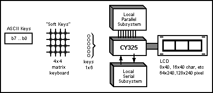 The
CY325 can detect key closures and announce them to the host. The meaning
of each "soft" key can be derived from a menu displayed on the
LCD, thus providing almost infinite flexibility. The key switches can be
ASCII, 4x4 matrix, or switches, depending on the key mode selected. A "positive
interlock" with the host is provided.
CY325 "System Element"
The CY325 can transfer data between the parallel and serial channels and thus link local parallel and serial subsystems to each other as well as to the LCD.
CY325/CY233 Network Displays
With built-in interface support for the CY233 Network Controller, the CY325 LCD controller allows up to 255 local stations to communicate with one host via RS-232 communications.

CY325 Interface to Computer or Host uC
Parallel Interface
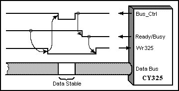 When
the master detects the CY325 ready to accept input (Ready = hi) it lowers
Wr325 to request transfer. The CY325 lowers Bus_Ctrl to signal the Bus
is available, then lowers Ready to signal completion of transfer (busy
with data). Bus_Ctrl can either be tested by software or simply used to
control tri-state outputs.
Serial Interface
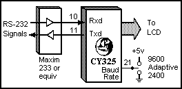 The
CY325 provides TTL-level transmit and receive lines, and requires only an
RS232 driver to provide an RS-232-level interface. The Baud rate pin
selects 2400 (lo), 9600 (hi), or adaptive (floating) in which two carriage
returns are sent to the CY325, which then matches the baud rate.
CY325 Interface to LCD
   CY325
    DIP      LCD
    Pin#     Pin#
    40       3      5 volt
    20       2      Ground
    16       5      WR_LCD
    17       6      RD_LCD
    22      19      Font Size #
    26       7      LCD enables
    27       8      LCD command
    28      10      LCD reset
    39      11      Data 0
    38      12      Data 1
    37      13      Data 2
    36      14      Data 3
    35      15      Data 4
    34      16      Data 5
    33      17      Data 6
    32      18      Data 7
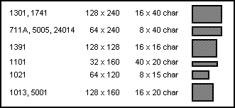
The CY325 is designed to work with a variety of different LCDs available from AND company, Densitron, Optrex, Samtron, Stanley, Standish, Sharp and Toshiba, which use the T6963C pixel driver. Some of the LCD displays tested with the CY325 are listed below with their formats.
CY325 Windows, Viewports, and Boxes
WINDOWS possess both character and pixel coordinate systems as shown below. BOXES posses only pixel coordinates. Boxes and windows are specified by defining their top left corner and lower right corner, with window corners expressed in character coordinates and box corners in pixel coordinates. A VIEWPORT is simply a "built-in" window whose size and location is implicitly defined. A viewport is identified by a number. The relevant commands are:
        Vn[cr]          n - viewport ID number
        Wx1y1x2y2[cr]   x,y = character coordinates
        Bx1y1x2y2[cr]   x,y = pixel coordinates
CY325 Coordinate Systems
 The
CY325 uses character and pixel coordinate systems. Text origin is upper
left (like IBM PC) while graphics origin is lower left (like algebra).
Although defined in global (LCD based) coordinates, the current box or
window establishes a local pixel coordinate system with the (0,0) origin
at the lower left corner.
CY325 Mode Registers
The CY325 operational mode depends on numerous mode bits grouped in registers. The two dozen mode bits are described in the Cybernetics CY325 user manual. Mode registers can be loaded via the 'M reg, value [cr]' command and queried by the '?' command.
        Register#       Description

        Primary Status Registers
             0          Window Status
             1          LCD Mode
             2          Key Mode
             3          Communications
             4          Key Image
        Current Window
             5          Viewport #
        Character Cursor
             6          Cursor Row
             7          Cursor Col
        Current Window Specification (Char. Coordinates)
             8          Top Row
             9          Left Col
            10          Bot Row
            11          Right Col
        Current Window Graphic Coordinates (Global)
            12          x1 Left Pixel
            13          y1 Top Pixel
            14          x2 Right Pixel
            15          y2 Bottom Pixel
        Window Save Status Registers
            16          Save View #
            17          Save Row
            18          Save Col
            19          Save Status
CY325 Prototyping Support
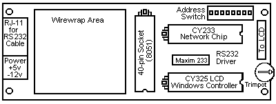
A prototyping kit for the CY325 is available from Cybernetic Micro Systems. The CYB-003 LCD Prototyping Kit will support one CY325, and one CY233 Local Network Controller, and also provide an 8051 socket and wirewrap area along with all connectors and relevant hardware. The board format is identical to the 711 LCD format.
CYB-003 Functional Diagram
CY325 Electrical Specifications
Absolute Maximum Ratings
  Ambient Temperature under bias .............. 0°C to +70°C
  Storage Temperature ......................... -65°C to +150°C
  Voltage on any pin with respect to ground ... -0.5V to Vcc+0.5V
  Power dissipation ........................... 0.2 Watts
DC & Operating Characteristics
(TA = 0°C to +70°C, Vcc = +5V +/-10%)
| SYM | PARAMETER | MIN | MAX | UNIT | REMARKS |
| I CC | pwr supply current | 20 | mA | ||
| V IH | input high level | 1.9 | Vcc | V | (3.5V for XTAL, Restart) |
| V IL | input low level | -0.5 | 0.9 | V | |
| I LO | data bus leakage | 10 | uA | high impedance state | |
| V OH | output high level | 2.4 | V | I OH = -60 uA | |
| V OL | output low level | 0.45 | V | I OL = 1.6 mA | |
| F CY | crystal frequency | 3.5 | 12 | MHz | see clock circuits |
LCD Displays Compatible with the CY325
![[LCD Chart]](gif/sdisplay.gif)
Zoom In For More Information on AND, Toshiba,
Optrex & Densitron Displays
![[Logo]](gif/smlogo2.gif) Cybernetic Micro Systems
Cybernetic Micro Systems
![PRODUCTS [Products]](gif/barprod.png)
![PRICES [Prices]](gif/barprice.png)
![SALES [Sales]](gif/barsales.png)
![COMPANY [Company]](gif/barcorp.png)
![HOME [Home]](gif/barhome.png)
![[LCD Display]](gif/lcd1.gif) ....Product Overview
....Product Overview ![[Commands]](gif/cmd.gif) ....Command Summary
....Command Summary ![[Pinouts]](gif/pinout.jpg) ....Pin Descriptions
....Pin Descriptions ![[Electrical Specs]](gif/elect.gif) ....Electrical Specifications
....Electrical Specifications ![[Logic]](gif/logic.gif) ....Logic Diagram
....Logic Diagram ![[CYB-003 Proto Board]](gif/lcdkit1.gif) ....Prototyping Board
....Prototyping Board ![[Support Software]](gif/disks1.gif) ....Support Software
....Support Software